 Urban / Government
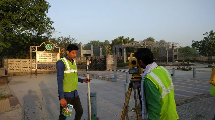
Delhi Zoological Park — Topographic & GPR Survey
Topographic PlanContoursSubsurface Feature MappingCAD Drawings
Client CPWD
CPWD
CPWD
Non-destructive subsurface investigation using radar pulses to locate buried utilities, structures, voids and layer interfaces, executed for CPWD and DDA.
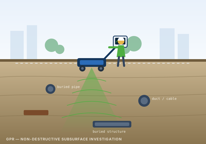
Ground Penetrating Radar is a non-destructive geophysical technique for investigating what lies beneath a surface without breaking it. A transmitting antenna sends short electromagnetic pulses into the ground; wherever those pulses meet a change in material — a pipe, a cable, a slab edge, a void, or an interface between two soil layers — part of the energy is reflected back and recorded. As the antenna is moved along a survey line, the accumulated reflections build a continuous vertical profile of the subsurface, from which buried utilities, structures and anomalies can be located in plan and estimated in depth. Bearing Technology deploys GPR where excavation is undesirable or impermissible: live campuses, heritage and institutional premises, landscaped and forested areas, operational roads, and congested urban sites where the risk of striking an unrecorded service is the principal project constraint.
Bearing Technology has executed GPR survey assignments for the Central Public Works Department at the Delhi Zoological Park, and for the Delhi Development Authority in the Delhi area — sites where subsurface information was required without disturbing surface features, mature landscaping or ongoing operations. Our approach treats GPR as an investigation method rather than a detection gadget: survey lines are laid out on a systematic grid tied to project control, antenna selection is matched to the ground conditions and target depth, depth conversion is calibrated on site rather than assumed, and interpretation is corroborated against surface evidence and available records. Deliverables are issued in CAD and GIS formats compatible with the client's design workflow, with the confidence attached to each detection stated explicitly so that design and excavation decisions rest on a clear understanding of what the data supports.
BTPL uses Ground Penetrating Radar (GPR) to investigate what lies beneath a surface without excavation, locating buried utilities, structures, voids and layer interfaces for:
The survey begins with a site walkover and a review of available records — existing utility drawings, as-built plans, chamber and valve locations, and known service corridors. Surface evidence such as manholes, inspection chambers, marker posts, hydrants and pole positions is noted, since it constrains the likely alignment of buried services. Access constraints, surface type, traffic movement and areas of restricted working are identified at this stage, and the survey grid or line layout is planned to give complete coverage over the area of interest.
A local control framework is established using DGPS/RTK observations tied to the project datum, so that every detection is reported in the client's coordinate system rather than in isolated site measurements. Where the survey runs inside buildings or under cover, a taped or total-station grid is set out and connected to the external control. Survey lines are laid out systematically — typically as orthogonal sets in both directions — with line spacing chosen to suit the expected target size and the required confidence of detection.
Antenna frequency is selected on site after trial passes, balancing required penetration depth against the resolution needed to separate closely spaced targets. Time window, gain and sampling settings are configured for the observed ground response, and the survey wheel or distance encoder is calibrated. Data is then acquired by traversing each planned line at a controlled and consistent speed, with line identity, direction and start and end positions logged. Surface obstructions and any locations where coverage could not be achieved are recorded in the field log.
Depth conversion in GPR depends on the propagation velocity of the radar signal through the ground, which varies with soil type and moisture content. Velocity is therefore calibrated on site rather than assumed — by hyperbola fitting on well-defined point reflectors within the recorded data and, where available, by referencing a service of known depth exposed at a chamber, trial pit or existing excavation. The adopted velocity and the basis on which it was derived are recorded so that every reported depth can be traced back to its calibration.
Recorded profiles are processed to improve interpretability — time-zero correction, background removal, gain adjustment and filtering, with migration applied where appropriate. Interpretation identifies hyperbolic responses from linear services and point targets, and continuous reflections from layer interfaces, voids and structural boundaries. Detections are correlated across intersecting lines to establish alignment and continuity, then transferred to plan. Interpreted positions are marked on the ground for the client's excavation team where required, and each detection is assigned a confidence category reflecting the clarity of its response and the degree of corroboration available.
"GPR is a powerful investigation tool, but its performance is governed by ground conditions and this must be understood before the results are relied upon. Radar energy propagates well through dry, resistive materials such as sand, gravel, dry made-up ground and sound concrete, and poorly through electrically conductive materials — clay-rich soils, saline ground, and heavily saturated or waterlogged strata — where attenuation can sharply reduce the achievable investigation depth. Reinforced concrete, dense rebar mats and shallow metallic clutter can mask targets lying beneath them. For this reason we do not quote a fixed detection depth or a universal accuracy figure in advance: the penetration achieved on site is established by trial passes and reported for the conditions actually encountered. Depth estimates are inherently a function of the radar propagation velocity through the intervening ground, so velocity is calibrated on site — by hyperbola fitting on identifiable point reflectors and, wherever possible, against a service of known depth exposed at a chamber or trial pit — and the calibration basis is recorded with the results. Plan positions, which are controlled by survey geometry rather than by ground properties, are generally more dependable than depth estimates. GPR indicates the presence, position and approximate depth of an anomaly; it does not by itself identify the material or ownership of a detected service, and non-metallic, small-diameter or deeply buried utilities may not produce a distinguishable response. Every detection is therefore reported with a confidence category, areas of poor or no penetration are shown as such rather than left blank, and the survey report states its limitations plainly. Where certainty is required before excavation, we recommend that interpreted positions be verified by trial pits or vacuum excavation at selected locations — which also serves to confirm the depth calibration — and that safe-dig practice governs the final excavation in all cases."
Urban / Government
CPWD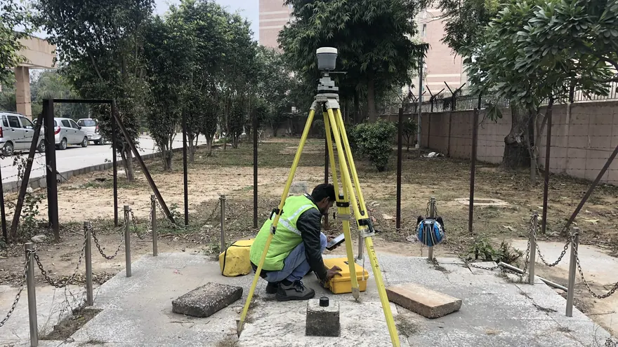 Urban Development
 DDA
DDAGPR is a non-destructive technique. Radar pulses are transmitted into the ground from an antenna moved along the surface, and the energy reflected from buried objects and material interfaces is recorded as a continuous profile. Because no excavation or coring is required, the method suits sites where digging is restricted — operational premises, heritage precincts, forested or landscaped areas, and live roads and pavements. It also allows a large area to be screened quickly so that any subsequent excavation is targeted rather than exploratory.
There is no fixed depth for GPR — penetration is governed by antenna frequency and by the electrical properties of the ground. Dry sands, gravels and sound concrete allow deeper penetration, while clay-rich, saline or water-saturated soils attenuate the signal strongly and reduce effective depth. Lower-frequency antennas reach deeper but resolve smaller targets less clearly; higher frequencies give sharper detail over a shallower range. We select antenna frequency after an on-site trial and state the investigation depth achieved in the actual ground conditions, rather than quoting a generic figure in advance.
GPR indicates the position and estimated depth of subsurface anomalies; it does not identify what an anomaly is made of or who owns it. Interpretation combines the radar response with corroborating evidence — visible surface features such as chambers, valves and marker posts, available utility records, and correlation with adjacent detections across intersecting survey lines. Where positive identification is required, the interpreted positions are used to plan safe trial pits or vacuum excavation at selected points, which also serves to verify the depth calibration.
Tell us the location, the approximate area or corridor length, and the deliverables you need — we will respond with the appropriate methodology and a clear proposal.